Building an Ultra Wide Band Log-Periodic Dipole Array
Antenna design is always an exercise in compromises. You can never make one optimization without sacrificing something else. In other words: there’s no perfect antenna. So when building a new one, you always need to think about what problem it is that this antenna will solve. For me, I wanted one antenna with reasonable gain, but extremely wide bandwidth. What can I say; I just don’t like unplugging my antennas.
Given that the goal is signal bandwidth, the obvious choice is a log-periodic dipole array. As the name suggests, a log-periodic dipole array is a bunch of dipoles connected to each other in an array. We’ll get to the log-periodic part later.
Basically, the way you can think of a LPDA working is that for each dipole in the array, it has a characteristic frequency (actually, an infinite family of them) at which it resonates. As long as the frequencies you want to use are close to one of these, it should work okay. The following image (which is creative commons licensed ;) ) summarizes how they work:
The parameters of an LPDA
The trade-off we make with an LPDA comes in two categories - gain and directionality. While an LPDA is a directional antenna (much more radiation comes out the narrow end than the wide end), it’s hardly the laser equivalent of a stacked Yagi-Uda or other beam antenna. It’s more like a floodlight that generally points one direction. And it’s also like a floodlight in that I wanted to make it cover both 2m and 440. I chose to aim to make it work from 100-500MHz, which is quite a wide range.
To help with this, I used this calculator to create the specs and made a simple drawing (on a piece of paper that I have since lost). To help with my bandwidth challenges, I opted to use 1/2 inch hollow copper tube for my antenna elements. This is much, much wider than most people use for LPDA antennas, but I thought it had two advantages:
It looks cool as hell
The wider the conductors, the more tolerant of slightly off-resonant signals they are, which increases bandwidth
I went with 13 elements after doing some soul searching.
The cut copper tube ready to become an antenna
This is the cut copper tube. You can see why they call it a log-periodic array. The elements vary logarithmically in both length (as shown here) and in placement (shown in the next image). The working theory here is that basically the longer an element is, the wider it’s acceptably resonant frequency range is. So the shorter elements need to be placed closer together to cover the same region of the spectrum.
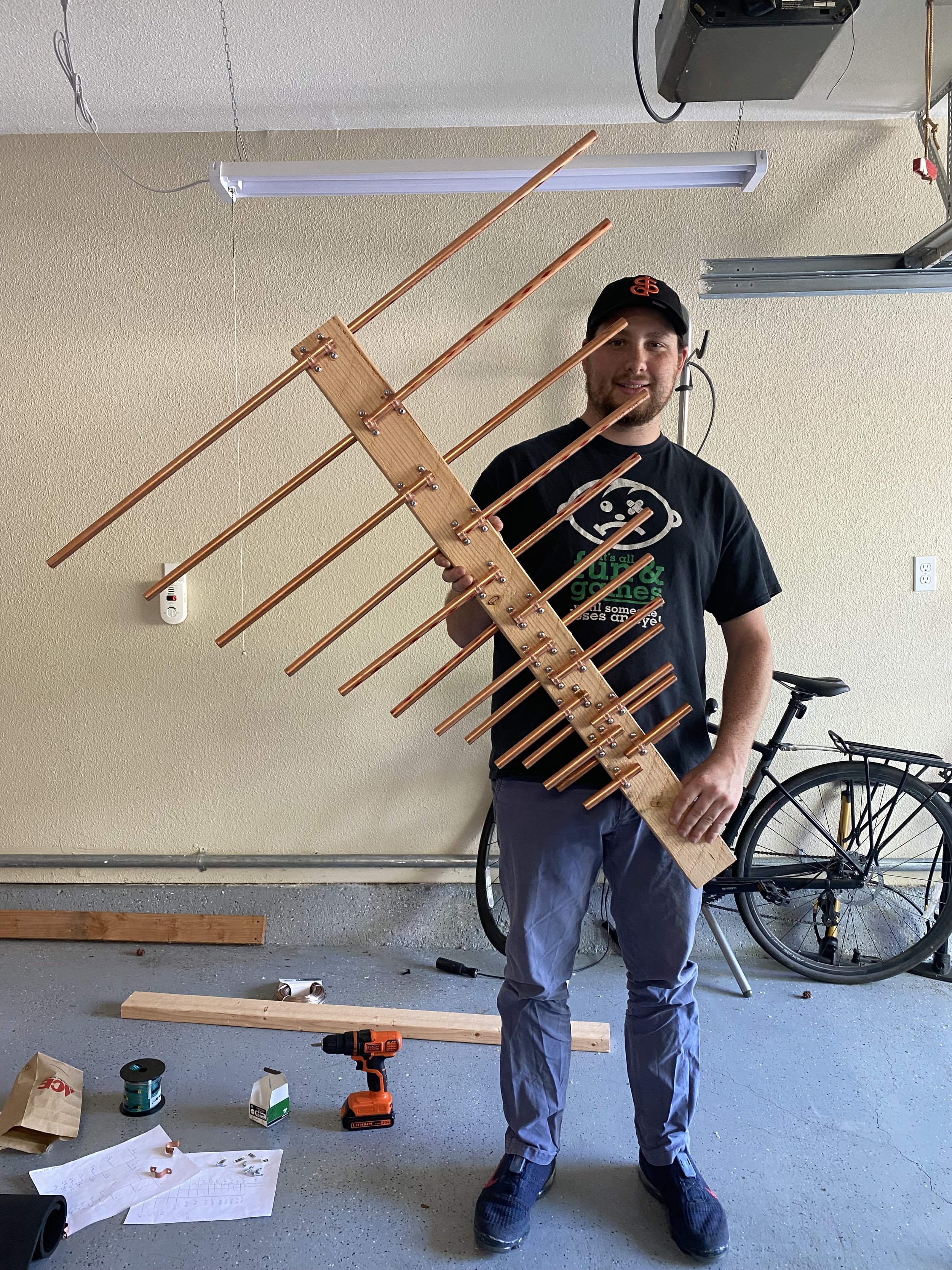
The elements mounted to our wooden boom.
The above image shows the logarithmic placement of the antenna elements along our 2x4 boom.
The antenna after it’s been wired up
This is the antenna with the elements soldered together. I hadn’t taken any pictures of the antenna with the 1:1 balun leading to the coax feed-line, and I actually still don’t have any. But it works pretty well for RX without it, and even better now that there is a balun. I built a stand and used liquid electrical tape to insulate the joints.
Overall, I had pretty good results with this antenna. It performs well across 100-500 MHz, as intended (of course, I have only tested TX on the ham bands around 145 and 440 MHz). It has reasonable gain (a little over 10 db front to back ratio), and I’m able to get great signal to all the local repeaters.
We’ll sign off with the above picture of the antenna on its stand, and me holding it (human for scale).
Holding the LPDA pre-wiring.


